Executive Summary
The telecommunications industry is undergoing a fundamental transformation. After decades of building terrestrial mobile networks, the industry's next frontier is the sky. Non-Terrestrial Networks (NTN) extend 5G New Radio (NR) beyond the Earth's surface, connecting satellites, high-altitude platforms, and ground infrastructure into a unified, global communication fabric.
The strategic imperatives driving NTN adoption are clear:
- Global coverage gaps: Over 80% of the Earth's geographic surface remains unserved by terrestrial mobile networks.
- Resilience and redundancy: Satellite overlay networks provide critical backup for disaster recovery and national security.
- Emerging IoT and M2M markets: Maritime, aviation, agriculture, and logistics industries urgently require ubiquitous connectivity.
- Regulatory momentum: Spectrum regulators worldwide (ITU, FCC, CEPT) are actively allocating dedicated bands for NTN.
3GPP Release 18, finalized in 2023–2024, introduces the definitive NTN framework — specifying architecture options, frequency bands, channel configurations, and propagation delay handling. This article distills those specifications into actionable insights.
1. What Is a Non-Terrestrial Network?
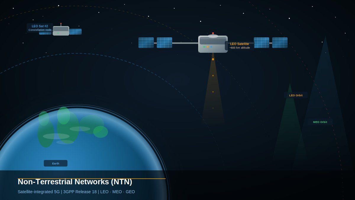
Non-Terrestrial Networks (NTN) refer to communication networks — or segments of networks — that rely on aerial or orbital platforms rather than traditional ground-based towers. These platforms include satellites in various orbital regimes and Uncrewed Aircraft Systems (UAS), also known as High Altitude Platform Stations (HAPS).
NTN is not a replacement for terrestrial networks (TN) — it is a complement. The vision is seamless integration: a user device should be able to transition between a ground cell tower and a satellite link without interruption, using the same 5G NR radio protocols.
1.1 Orbital Classes
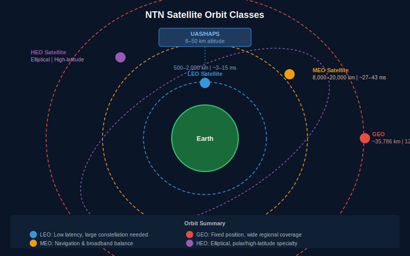
NTN encompasses four principal orbital configurations, each with distinct trade-offs in latency, coverage, and cost:
| Orbit | Altitude | One-Way Delay | Key Characteristic |
|---|---|---|---|
| LEO | 500 – 2,000 km | 3 – 15 ms (max 30 ms) | Low latency; requires large constellation for global coverage |
| MEO | 8,000 – 20,000 km | 27 – 43 ms (max 90 ms) | Balance of coverage and latency; used for navigation systems |
| GEO | ~35,786 km | 120 – 140 ms (max 280 ms) | Fixed position; wide regional footprint; high latency |
| HEO | Elliptical | Varies | Specialty coverage for polar and high-latitude regions |
| HAPS/UAS | 8 – 50 km | < 1 ms | Near-terrestrial; quasi-stationary over target area |
Table 1: NTN Orbital Class Comparison
1.2 Why NTN Now?
The confluence of falling launch costs (driven by reusable rockets), advances in software-defined radio, and the maturation of 5G NR standards has made NTN commercially viable at scale. Operators such as SpaceX (Starlink), Amazon (Project Kuiper), and Eutelsat OneWeb are already deploying LEO mega-constellations, while 3GPP Release 18 provides the standardization framework to integrate these constellations into licensed cellular networks.
2. NTN Architecture Options
3GPP Release 18 defines four primary architecture options for integrating satellite or aerial platforms into the 5G New Radio (NR) access network. The choice of architecture has profound implications for cost, latency, on-board processing requirements, and regulatory compliance.
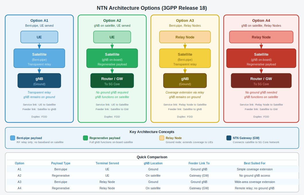
2.1 Option A1 — Bent-Pipe Relay, UE-Served
In this configuration, the satellite acts as a transparent relay (bent-pipe payload). It simply amplifies, frequency-converts, and re-transmits the radio signal between the ground-based gNodeB (gNB) and the User Equipment (UE). All intelligence — scheduling, baseband processing, and core network interfacing — resides on the ground.
- Satellite payload: Remote Radio Head (transparent relay of Uu interface)
- gNB location: Ground (NTN Gateway)
- Best suited for: Established satellite operators adding 5G NR access with minimal on-board development
- Trade-off: Round-trip delay is doubled compared to A2, as signal must travel to ground gNB and back
2.2 Option A2 — Regenerative Payload, UE-Served
The satellite incorporates all or part of a gNB (or Relay Node) on-board. The satellite generates and processes the 5G NR signal directly, eliminating the need for a ground gNB for the access segment. The gateway connects the satellite to the 5G Core Network.
- Satellite payload: On-board gNB or Relay Node (regenerative)
- gNB location: On satellite
- Best suited for: Scenarios where ground gateway accessibility is limited; reduces feeder-link latency
- Trade-off: Requires significant on-board processing; higher development complexity for satellite manufacturers
2.3 Option A3 — Bent-Pipe Relay, Relay Node-Served
Similar to A1, but the terminal served is a Relay Node rather than a direct UE. The Relay Node further extends coverage to end-user devices. This architecture is optimized for coverage extension scenarios — reaching areas beyond the satellite footprint.
- Satellite payload: Transparent bent-pipe relay
- Terminal served: Relay Node (which then serves UEs)
- Best suited for: Wide-area coverage extension in maritime, rural, or disaster-recovery deployments
- Trade-off: Additional cost of Relay Node deployment; increased latency chain
2.4 Option A4 — Regenerative Payload, Relay Node-Served
The most capable and complex option: the satellite hosts gNB or Relay Node functions on-board, and serves ground-based Relay Nodes. This eliminates the dependency on a ground gNB entirely, making it suitable for the most remote deployments where even a gateway may be intermittently available.
- Satellite payload: On-board gNB or Relay Node functions
- Terminal served: Relay Node
- Best suited for: Truly isolated environments with no ground network infrastructure
| Option | Payload Type | Terminal Served | gNB Location | Complexity | Best For |
|---|---|---|---|---|---|
| A1 | Bent-pipe | UE | Ground | Low | Simple coverage extension |
| A2 | Regenerative | UE | On satellite | High | No ground gNB access needed |
| A3 | Bent-pipe | Relay Node | Ground | Medium | Wide coverage, relay-based |
| A4 | Regenerative | Relay Node | On satellite | Very High | Fully remote deployments |
Table 2: NTN Architecture Options Summary
3. NTN Spectrum and Channel Allocation
Spectrum is the lifeblood of any wireless network. 3GPP Release 18 defines dedicated NTN frequency bands within both FR1 (sub-7 GHz) and FR2 (millimeter-wave) ranges, distinct from but aligned with the broader 5G NR band plan.
3.1 Frequency Ranges
| Range | Designation | Frequency Span | NR Equivalent |
|---|---|---|---|
| Sub-6 GHz | FR1-NTN | 410 MHz – 7,125 MHz | FR1 |
| Ka / Ku Band | FR2-NTN | 17,300 MHz – 30,000 MHz | FR2 |
Table 3: NTN Frequency Ranges
3.2 FR1-NTN Satellite Bands
Three operating bands are defined for FR1-NTN, all using Frequency Division Duplex (FDD):
| Band | Common Name | UL (UE Transmit) | DL (UE Receive) | Notes |
|---|---|---|---|---|
| n256 | S-Band | 1980 – 2010 MHz | 2170 – 2200 MHz | IMT-MSS allocation; global roaming potential |
| n255 | L-Band | 1626.5 – 1660.5 MHz | 1525 – 1559 MHz | Established Inmarsat / Iridium band region |
| n254 | MSS Band | 1610 – 1626.5 MHz | 2483.5 – 2500 MHz | Asymmetric BW supported; MSS applications |
Table 4: FR1-NTN Satellite Operating Bands (Conducted Requirements)
3.3 FR2-NTN Satellite Bands
Three Ka-band operating bands are defined for FR2-NTN, with regional applicability governed by CEPT and FCC:
| Band | UL (UE Transmit) | DL (UE Receive) | Regulatory Scope |
|---|---|---|---|
| n512 | 27,500 – 30,000 MHz | 17,300 – 20,200 MHz | CEPT ECC Decision (05)01 and (13)01 countries |
| n511 | 28,350 – 30,000 MHz | 17,300 – 20,200 MHz | FCC 47 CFR Part 25 (USA and aligned jurisdictions) |
| n510 | 27,500 – 28,350 MHz | 17,300 – 20,200 MHz | USA Earth Station operations (no ESIM per FCC) |
Table 5: FR2-NTN Satellite Operating Bands (Radiated Requirements)
3.4 Channel Bandwidth and Subcarrier Spacing
The subcarrier spacing (SCS) and channel bandwidth configurations define spectral efficiency and capacity:
FR1-NTN Bandwidth Configuration
| Band | SCS Options (kHz) | Supported UE Channel Bandwidths (MHz) |
|---|---|---|
| n256 | 15 / 30 / 60 | 5, 10, 15, 20 |
| n255 | 15 / 30 / 60 | 5, 10, 15, 20 |
| n254 | 15 / 30 / 60 | 5, 10, 15 (asymmetric UL/DL for n254) |
Table 6: FR1-NTN SCS and Channel Bandwidths
FR2-NTN Bandwidth Configuration
| Band | SCS Options (kHz) | Supported SAN Channel Bandwidths (MHz) |
|---|---|---|
| n512 | 60 / 120 | 50, 100, 200 (60 kHz); 50, 100, 200, 400 (120 kHz) |
| n511 | 60 / 120 | 50, 100, 200 (60 kHz); 50, 100, 200, 400 (120 kHz) |
| n510 | 60 / 120 | 50, 100, 200 (60 kHz); 50, 100, 200, 400 (120 kHz) |
Table 7: FR2-NTN SCS and SAN Channel Bandwidths
Asymmetric channel bandwidth operation is supported in FDD mode. For n254, the narrower carrier must be confined within the frequency range of the wider channel bandwidth, with the maximum center frequency deviation defined as:
4. Power Requirements and Propagation Delay
4.1 UE Minimum Output Power
The minimum controlled output power of the UE is defined across all transmit bandwidth configurations:
| Channel BW (MHz) | Minimum Output Power (dBm) | Measurement Bandwidth (MHz) |
|---|---|---|
| 5 | −40 dBm | 4.515 |
| 10 | −40 dBm | 9.375 |
| 15 | −40 dBm | 14.235 |
| 20 | −40 dBm | 19.095 |
Table 8: UE Minimum Output Power (per 3GPP TS 38.101)
The minimum output power is measured as the mean power over at least one sub-frame (1 ms). This parameter is critical for uplink power control algorithms in NTN, where path loss variation is significant due to satellite orbital dynamics.
4.2 Propagation Delay
Propagation delay is one of the most significant engineering challenges in NTN, distinguishing it fundamentally from terrestrial networks. The 5G NR protocol stack — including HARQ timing, scheduling windows, and RRC procedures — requires adaptation to accommodate NTN delays.
| Orbit | UE-to-Sat Min (ms) | UE-to-Sat Max (ms) | One-Way Max (ms) | Protocol Impact |
|---|---|---|---|---|
| LEO | 3 | 15 | 30 | Minor HARQ timer adjustment; Near 5G NR baseline |
| MEO | 27 | 43 | 90 | Moderate; HARQ disabled or extended timers |
| GEO | 120 | 140 | 280 | Significant; HARQ disabled; long scheduling delays |
Table 9: NTN Propagation Delay by Orbit
For GEO-based NTN deployments, the one-way propagation delay of up to 280 ms means that applications requiring ultra-low latency (gaming, real-time voice) are not well-suited without additional protocol optimization. However, broadband data, IoT, and M2M applications tolerate these delays effectively.
5. Key NTN System Elements
| System Element | Description | Architecture Role |
|---|---|---|
| NTN Terminal | The 3GPP UE or satellite-specific terminal device used by the end user. | Generates/receives the 5G NR service link signal |
| Service Link | The radio link between the UE and the space/airborne platform. | Carries user data and control plane over the air interface |
| Space/Airborne Platform | Satellite or HAPS with either a bent-pipe or regenerative payload. | Relays or processes the NR signal |
| Bent-Pipe Payload | RF filtering, frequency conversion, and amplification only — no baseband processing. | Transparent relay; gNB remains on ground |
| Regenerative Payload | Full demodulation/decoding, switching/routing, and re-modulation. | Equivalent to on-board gNB functions |
| Inter-Satellite Links (ISL) | RF or optical links between satellites in a constellation (regenerative only). | Enables multi-hop routing without ground station reliance |
| NTN Gateway | Ground station connecting the satellite/aerial network to the 5G Core Network. | Terminates feeder link; interfaces to 5GC |
| Feeder Link | Radio link between the NTN Gateway and the space/airborne platform. | Backhaul for the NTN access segment |
Table 10: NTN System Elements and Their Roles
6. Strategic Implications and Deployment Considerations
6.1 For Executives and Decision-Makers
- Market opportunity: NTN enables operators to monetize previously unserviceable geographic areas, including maritime routes, aviation corridors, and rural regions across emerging markets.
- Investment calculus: LEO constellation deployments require significant capital expenditure but offer lower latency and higher throughput competitive with terrestrial broadband in remote areas.
- Regulatory readiness: Organizations planning NTN deployments must engage early with national telecommunications regulators, as band-specific licenses (particularly FR2-NTN) carry geographic constraints (CEPT vs. FCC applicability).
- Vendor ecosystem: The 3GPP Release 18 NTN framework creates a standardized interface, enabling multi-vendor interoperability — reducing lock-in risk compared to proprietary satellite communication systems.
- Hybrid network strategy: The most resilient enterprise and operator strategies will combine NTN overlay with existing terrestrial 5G networks, ensuring seamless handover and service continuity.
6.2 For Network Engineers and Architects
- Architecture selection: Match the NTN architecture option (A1–A4) to the use case — bent-pipe is simpler and lower-risk; regenerative payloads offer lower latency but require significant on-board processing investment.
- Timing and synchronization: NTN introduces large and variable timing advances. Implementations must support extended TA values (up to 67,108 Tc for LEO, up to 1,282,172 Tc for GEO) as specified in TS 38.211.
- Doppler compensation: LEO satellites moving at approximately 7.5 km/s introduce significant frequency offsets. Pre-compensation at the UE or satellite is required to maintain 5G NR waveform integrity.
- HARQ adaptation: For MEO and GEO orbits, HARQ round-trip times exceed the standard 8 ms window. 3GPP Release 17 introduced HARQ process extension and disabling mechanisms for NTN.
- Feeder link dimensioning: The gateway feeder link must be sized to handle peak aggregate traffic from all UEs within a satellite beam. FR2-NTN Ka-band feeder links can support up to 400 MHz bandwidth per carrier.
- Spectrum coordination: Operators must coordinate with incumbent users of L-band (n255) and S-band (n256) frequencies, as these bands have existing MSS and FSS allocations.
7. Conclusion
Non-Terrestrial Networks represent the next evolutionary step in global mobile communications. By integrating satellite and aerial platforms into the 3GPP 5G NR ecosystem, NTN extends the reach of standardized, high-quality mobile connectivity to every corner of the planet.
3GPP Release 18 provides a comprehensive and mature specification framework: four architecture options covering the full spectrum from simple bent-pipe relays to fully regenerative on-board gNBs; dedicated frequency bands in both FR1-NTN and FR2-NTN with FDD channel configurations up to 400 MHz; and detailed propagation delay parameters for LEO, MEO, and GEO orbits.
The coming decade will see NTN transition from a niche technology to a mainstream component of telecommunications infrastructure. Organizations that engage with these standards today — whether as operators, equipment vendors, or enterprise users — will be best positioned to lead in the connected world of tomorrow.
References and Further Reading
3GPP Standards
- 3GPP TS 38.101-5, "NR; User Equipment (UE) radio transmission and reception; Part 5: Satellite Access Radio Frequency (RF) and performance requirements," Release 18.
- 3GPP TS 38.104, "NR; Base Station (BS) radio transmission and reception," Release 18 — NTN Satellite Access Node (SAN) requirements.
- 3GPP TS 38.300, "NR; NR and NG-RAN Overall Description," Release 18 — NTN architecture overview.
- 3GPP TS 38.211, "NR; Physical channels and modulation," Release 18 — Timing advance and Doppler compensation for NTN.
- 3GPP TR 38.821, "Solutions for NR to support Non-Terrestrial Networks (NTN)," Release 16.
- 3GPP TR 38.863, "NTN enhancements for NR — Study on expanded NTN band plans," Release 18.
Regulatory References
- CEPT ECC Decision (05)01, "The use of the band 27.5–29.5 GHz by Earth Stations in Motion."
- CEPT ECC Decision (13)01, "Conditions for Earth Stations on Mobile Platforms (ESOMPS) operating in the 17.3–20.2 GHz and 27.5–30.0 GHz frequency bands."
- FCC 47 CFR Part 25, "Satellite Communications" — US regulatory framework for earth station operations in Ka-band.
Industry and Technical Resources
- 3GPP Official Website: www.3gpp.org
- ETSI, "Non-Terrestrial Networks (NTN) — Overview and Architecture," White Paper, 2023.
- ITU-R, "Handbook on Satellite Communications," 4th Edition, International Telecommunication Union, Geneva.
- GSA (Global mobile Suppliers Association), "Non-Terrestrial Networks: Status Update," 2024.
Views expressed are the author's own and do not represent any employer or organization.